Canyon Pounder Installation and Setup
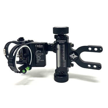
Canyon Pounder Sight: Installation and Operation
Included with each CP: Reference Scales (Installed), 2 Pages of Sight Tapes, Allen Wrench Set, Mount Screws.
1. Attach to Bow: We have provided mounting screws (b). Extension Mount Block uses 1" long attach screws and the Direct Mount uses 1/2" long attach screws. Pic Rail and Bridge-Lock extension mounts DO NOT include attach screws. Using bow string wax on the bow attach screw threads can help with locking them down smoothly.
2. Windage and Elevation Adjustments: Adjust the windage to set your sight for approximate center-shot before you start shooting. To adjust the windage gang adjustment; loosen the lockdown screw (k), then adjust by turning the micro-click-knob (g), turning the knob clockwise will move the sight pins toward the knob. Lockdown screw (k) can be moved to the appropriate hole in the windage block (4 total holes) to increase the adjustment range right or left (if/when you run out of adjustment in the current hole). Snug down the lockdown screw (k) after adjustment. To adjust the elevation gang adjustment you will need to loosen the lockdown screw (f) and slide the assembly up or down. Lockdown screw (f) can be moved to the next hole (higher or lower) to increase total travel. To adjust the elevation more than a short distance, there are two additional options for larger elevation adjustments; first option is to remove both (c) screws, and re-attach them into the appropriate set of threaded holes (higher or lower). Second option is to remove the 4 (h) screws (used for 2nd axis leveling of pinguard, discussed below) and re-install in the appropriate set(s) of threaded holes. To utilize the full vertical travel of the sight, adjust so the helix drive is at the top of the travel range when set for your closest yardage (usually 20 yards/meters).
3. Check/Adjust Mover Pin Alignment with Fixed Pins: When the sight is assembled we set the mover pin to line up with the fixed pins (for windage), but each of us hold our bow differently, so you will need to check this. Draw your bow and see if the mover pin is lined up perfectly (left/right) with the fixed pins. If it is slightly left or right, open the pinguard, and loosen screw (l) that locks the mover pin. This will allow you to move the pin left or right, then lock the screw back down, don't over-tighten this screw! This adjustment will only need to be made once for each bow/archer combination.
4. Level the Sight to Your Bow for 2nd Axis: First step is to level the helix drive system to your bow, this is accomplished by slightly loosening both (c) screws. This allows you to rotate the vertical drive against the mount bar, then lock the (c) screws back down. Second step is to level the pinguard assembly to the vertical drive system, this is accomplished at the screws (h). By loosening either the top two (or bottom two) (h) screws, and tightening the other two, the sight is leveled. Once leveled, snug all four screws down. Do not over-tighten.
5. Selecting the Correct Sight Tape: By using the elevation adjustments (described above) you can sight in with the mover pin at 20 (top of the adjustment range). This will put your 20 at the "00" on the laser engraved sight scale. Next, shoot your way back to the yardage you wish to use for selecting the correct tape. The Reference Scale Selection Table (on the 2nd sight tape sheet) allows for tape selection at either 50 (yards/meters) or 80 (yards/meters).

After you shoot enough (at either 50 or 80) to be confident in the setting, see where your sight is set (on the reference scale). Use the Selection Table to select the appropriate tape. Example: if you shot at 80 yards and found that your sight is set at "84" on the reference scale, the selection table says you need tape #26. There are two tapes, one for the main sight tape surface, and the other (narrow one) for the backside "2nd" reference surface. We recommend that this 2nd sight tape be used for one of your fixed pins (usually the bottom one). You can now remove the correct sight tape(s) by cutting them out of the sight tape sheet and peeling the sight tape from the backing, then install on the sight. For the main sight tape location either flip the aluminum scale over and stick the sight tape to the back, or remove the reference scale and stick the sight tape directly to the sight itself. FOR THE BACK SIGHT TAPE: you will probably want to remove the aluminum scale, and stick the sight tape directly to the vertical guide face, there may not be enough clearance under the indicator blade for the tape on top of the aluminum scale. Note: After selecting the sight tape, and shooting for several practice sessions, you may find you need to adjust slightly by moving to a different tape. The increments between the tapes are small.
ALUMINUM SPEED SPECIFIC SIGHT SCALES: Once you have shot enough to determine for sure what tape(s) you want to use, if you would like the appropriate laser engraved scale, we will have aluminum laser engraved scales available for purchase separately.
6. Set Your Fixed Pins: To adjust the fixed pins, open the fixed pinguard and adjust with screws (m). Care must be taken to not over-tighten these screws. Make sure the pin you are adjusting is staying parallel to the other pins as you tighten the screw, it helps to hold the pin straight while snugging the screw down. DO NOT OVER-TIGHTEN.
7. 3rd Axis Leveling: Leveling with the standard 3rd Axis Adjustment (at the level bracket): Leveling your sight for 3rd Axis will give you confidence for up and down hill shots. If you have a 3rd Axis leveling device this works well, if you do not have one this sight allows you to "sight-in" your 3rd Axis. Using either and uphill or downhill target, shoot your first arrow aiming at the spot (with bubble held level). If your arrow impacts either left or right, slightly loosen the screw (n) on one side of the bubble, and tighten the other screw (n) the same amount. Continue to adjust in small increments until your arrow impacts in the center (left/right). Snug down the screws, don't over-tighten.
OPTIONAL BAR MOUNTED 3RD AXIS ADJUSTMENT BLOCK is available. For most setups this optional adjustment block will not be needed, but (especially when using lenses on the sight) you may like having this extra adjustment to level the "face" of the housing/lense to your eye.
8. Tension Adjust for Helix Drive: We pre-set the tension of the helix drive to what we feel is optimal, if you want to increase (or decrease) the resistance on this adjusment, this can be adjusted. The Large (top) drive knob is threaded onto the helix drive rod. To adjust, loosen the set screws (e) in the adjustment knob, and tighten/loosen the knob 1/6th of a rotation while holding the bottom knob (to hold the helix rod from rotating), then snug the set screws back down. These are flat tip set screws that are locking against "keyed" surfaces on the helix rod (similar to the surfaces of an allen-wrench), so increments are approximately 1/6th rotation, lock setscrews against flat sides.
9. Maintenance and Lights: This sight is designed to be virtually maintenance free, and is covered by our lifetime warranty, but if you ever feel like you need to clean the helix drive system, simply loosen the set screws (e) and remove the large top adjustment knob. This will allow you to remove the helix rod by threading it out the bottom of the housing. It is easy to clean by spinning it through a cloth, or even your fingers. This cleaning will not change your sight settings. We offer optional lights that can be attached to the fixed pin light adapter (j) for fixed pins and/or light attach at (i) for the mover pin. Lights, Lenses, Adapters, and other accessories can be purchased here on the website.
LIFETIME WARRANTY - Don't hesitate to reach out if you have any issue! Feel free to e-mail Dan dierct with any tech questions: dan@optionarchery.com , or contact the office at (406)827-0603 or info@optionarchery.com.

© 2026 Option Archery